
 In the previous blogs of this series, we highlighted that the properties of the film are central to the design of a deposition instrument, with film thickness and uniformity being critical parameters for performance. Throughput predictions help to determine and maximize the system ROI. Proper design can also identify and trim away unnecessary cost elements, reducing the “I” in ROI. In part 2, we examined design considerations for rotating substrate. This blog will look at coating methods for linear motion systems.
Industrial Coating Applications
Often, after a film material and process are developed in the lab, the system is ready for transfer to large-scale production. Some applications for continuous, high-volume production include coating of plates for optics, polymeric webs for flexible electronics and metal tape. In such cases, sputter-coating from a linear magnetron can be used. A conveyor translates the substrate at constant speed through the deposition zone, typically across the width of the magnetron. The photo below shows the interior elements of one of our reel-to-reel tape coating systems.
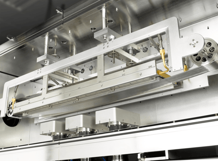 Image: Continuous tape coating by magnetron sputtering. In this case, nine passes are made through a deposition zone having three linear targets. The tape is kept cool by being passed over a water-cooled, bowed Inconel plate.
Three Design Drivers
For linear-motion coating systems there are three factors that drive the design. For illustrative purposes, let us consider a simple example of anti-reflective (AR) layer deposition on a plate to demonstrate the instrument design choices and the implications on performance.
- Deposition Material. The required material will influence the deposition technology. Let’s assume we are aiming for a 50-nm thick Al2O3 layer, deposited by RF sputtering. This will limit the growth rate compared to reactive sputtering, but for some applications, it is the preferred method.
- Thickness Uniformity. The application naturally drives the specification for film thickness, and the process engineer must also quantify the tolerable non-uniformity. For our AR layer, let’s look for ± 2% non-uniformity.
- Throughput. The finished-area coating rate is the product of the width of the substrate, the speed at which it passes through the deposition zone, and, optionally, the number of passes it makes through that zone. In our example we’ll consider coating a 24” wide plate using a 10 meter/hour substrate motion. To complete the design, we would need to know the time to complete the process and ultimately to tailor the process to match technical and economic requirements.
The tool for this example application is likely to have high capital cost and little flexibility in changing the sputtering geometry afterwards. It would be best to maximize the ROI by predicting where optimal performance is to be expected. Because it is difficult to do this intuitively, numerical modeling can be a useful design guide.
In our next and final post of the deposition rate and uniformity series, we'll explore numerical modeling of the above job. Have a project you want to talk through with us before then?
Send us your specs and we'll help you troubleshoot system design and configuration:

Leave a Comment